Optical Disc Technology
Introduction
Optical disc technology is a growing force in home video which became popular
with the introduction of the audio Compact Disc. Today, various formats exist,
which besides sound can also carry data, graphics and full motion video parts.
First we will take a look at the basics of the optical disc technology, and then
at some of the existing formats of optical discs and accompanying hardware. The
types of optical discs discussed in this handbook are Laserdisc (LD) and CD-i,
and to a lesser degree CD-ROM and Photo CD.
Digital Technology
Optical disc technology makes use of digital signal processing, contrary to
the analog audio and video carriers, such as the gramophone record and the
magnetic videotape. But why digital?
In analog transmission, any imperfection during the registration, storage or
reproduction phases of recording will decrease the quality of the audio and/or
video signal. For example, a dirty record causes noise, an irregular revolution
or winding speed causes problems, a worn needle or a dirty head causes
distortion. These imperfections do not occur in digital registration. (For more
detailed and in-depth information, please refer to the Audio Handbook, in which
the basic principles of the Compact Disc Technology are explained.)
From analog to Digital
In optical disc technology, analog signals are converted into digital
signals (with the exception of the video information on laserdiscs, as will be
explained later). During this process, the analog signal (audio and/or video)
is measured in parts and converted into a series of values, called sampling.
One can envision a waveform representing an audio or video signal, being
measured with intervals. The signal strength and polarity at these intervals
can be expressed in decimal numbers (1,2,3, etc.) and express the signal
strength and polarity (+ or -) from point to point. The frequency of how often
the signal strength is measured in a waveform, determines the accuracy of the
registration of the original waveform. These steps must therefore be very
small. The measurements are in the order of tenths of millivolts.
An analog-to-digital (A/D) converter translates these decimal values into
binary notation (bits). Bits are made up of '1's and '0's only, and by
combining these ones and zeros in different combinations, decimal numbers can
be expressed in binary notation. Some examples of binary notation (in 3 bits)
are:
     Decimal     Binary
     ------------------
     1           001
     2           010
     3           011
     4           100
     5           101
     6           110
     7           111
Thus the analog signal becomes a digital signal which is now a series of
pulses: pulses for the '1's, and non-pulses for the '0's. For optical discs
these pulse series are recorded on the surface of the disc as microscopically
small pits and lands, with the help of a fine laser beam. Pits stand for '0's
and lands stand for '1's. In most recordings every value (44,100 per second)
is converted into a string of 16 bits (instead of the three bits example).
This totals over one million bits per second. A 16-bit number of '1's and '0's
can indicate no less than 65,536 different values (2 values possible for each
bit = 216 = 65,536 possibilities). More information is available in the Audio
Handbook.
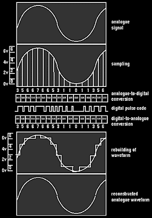
Conversion process of an analog signal to digital and back to
analog.
Scanning the Disc
Like gramophone records, the information on optical discs is recorded on a
spiral track. The laser starts 'reading' the disc from the inside and ends at
the outside. When played back, a laser beam shines on the pits and lands. When
the beam strikes a land, the beam is reflected onto a photoelectrical cell.
When it strikes a pit, the photo cell will receive only a weak reflection.
Thus the photoelectrical cell receives series of light pulses corresponding to
the pits and lands in the disc. A D/A-converter (digital to analog converter:
DAC) converts the series of pulses back to binary coding, and then to decimal
values. Now the original analog signal can be rebuilt.
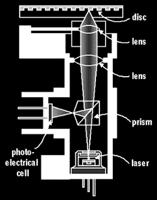
Cutaway view of the laser pickup. Depending on whether the laserbeam
hits a pit or a land, the laserbeam is reflected and received by the
photo-electrical cell.
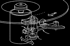
Compact Disc player mechanism. The laser pickup reads the disc from
below.
CIRC
Thanks to this optical scanning system, there is no friction between the
laser beam and the disc. As a result, the discs do not wear, however often
they are played. However, they must be treated carefully, as scratches, grease
stains and dust might intercept or diffract the light, causing whole series of
pulses to be skipped or distorted. This problem can be solved, as during the
recording the Cross Interleaved Reed Solomon Code (CIRC) is added, which is an
error correction system that automatically inserts any lost or damaged
information, by making a number of mathematical calculations. Without this
error correction system, optical disc players would not have existed, as even
the slightest vibration of the floor would cause sound and image distortions.
Laserdisc
The Laserdisc was developed by Philips as an advanced form of video. Just
like the CD-player, the Laserdisc player is characterized by simple principles
of operation, be it directly on the LD-player or via remote control.
Like the CD, the Laserdisc is scanned by a laser beam. In excess of one
million shallow pits in the disc per second are read one-by-one in the same way
as the CD. A Laserdisc-player can play back not only laserdiscs, but also audio
CDs. The main difference between laserdisc and other optical discs is that the
audio signal on Laserdiscs is recorded digitally, just like CDs, but that the
video signal is recorded in an analog way. Combining digital and analog
information makes efficient use of the available disc space, enabling longer
playing times than when all the information is digitized. analog video can offer
very good image quality, with sharpness and details better than the average
videotape reproduction. Due to the analog video processing, laserdisc still
depends on local television standards (for example a PAL disc cannot be read by
an NTSC player nor a NTSC disc by a PAL player). However, there are players that
can handle more than one system.
Laserdisc Sizes
Laserdiscs come in three sizes, each having a different application.
Laserdisc players can handle all sizes.
12 cm Laserdisc single
The small, gold or silver colored
Laserdisc single has a diameter of 12 cm, which is similar in size as the
CD. The Laserdisc single can contain 6 minutes of video programming plus
accompanying digital sound. Alongside the video information, it has space
for 20 minutes of digital audio.
The video program is recorded on the outer tracks of the Laserdisc
single, the audio program on the inside tracks. In this way the audio part
can also be played back via any existing CD player, because the CDs are read
from the inside to the outside. When a Laserdisc single is started, the
laser-pickup will move first to the video part. After having played back the
video part from the inner to the outer tracks, the laser will move
automatically to the inside of the disc and starts playing the audio track.
The Laserdisc single is an ideal carrier for video clips and music video.

Most
Laserdisc players are multi-disc players which can play several sizes of
laserdiscs and audio compact discs.
20 cm Laserdisc EP
For longer programs the Laserdisc EP
(Extended Play) was invented. An EP laserdisc can be double-sided, has a 20
cm diameter and can contain a maximum of 20 minutes of video plus audio per
side, making a total of 40 minutes on a double sided disc. When the disc has
two recorded sides, the disc actually consists of two discs glued together,
back-to-back. The Laserdisc-EP is especially suitable for music video clips,
cartoons, documentaries and instruction films.
30 cm Laserdisc LP
For complete concerts, films, operas, etc.,
the 30 cm Laserdisc LP was developed. This disc can contain a maximum of 60
minutes of video plus audio on each side, making a total of two hours. Here
too, the double-sided disc consists of two discs glued together. The
Laserdisc LP is the format used most often.
CLV and CAV
In audio Compact Discs, the scanning starts at the center at a speed of 500
revolutions per minute (rpm), which reduces as the beam moves towards the
outside edge where the speed is 200 rpm. This is the principle of the Constant
Linear Velocity (CLV), which means that the laser beam reads the disc at a
constant speed of 1.25 meters per second. CLV discs are also called Linear
Play discs.
The Laserdisc is also scanned at a constant speed, but at a much higher
speed of around 11 meters per second. If a conventional CD is inserted, the
player automatically starts at the standard speed of 500 rpm. The introductory
track of the disc tells the Laserdisc player which type of disc has been
inserted. The number of revolutions is automatically increased to 2700 rpm
when a Laserdisc single is inserted, and to 1800 rpm in the case of a
Laserdisc LP.
Apart from the conventional CLV (Linear Play) discs as described above,
there are also discs that have a Constant Angular Velocity (CAV discs), which
means that the revolutions per minute remain constant. The advantage of this
is that it allows fast and slow playback (at variable speeds, forward and
backward), still playback, repeat playback and fast track (within a number of
seconds) with the help of image and index numbers. As the number of
revolutions remains constant during playback, the scanning speed will decrease
as the laser-pickup approaches the outer tracks of the disc. CAV discs have
only half the playing times of CLV discs, as they make less efficient use of
the disc capacity. Contrary to the CAV disc, the conventional CLV disc does
not contain any image numbers. As with audio CDs, CLV discs can indicate the
playing time in hours, minutes and seconds. By indicating a start and a stop
point at the counter setting, musical pieces or scenes can be stored in memory
and be played back separately. CLV and CAV discs are available in both 20 cm
and 30 cm format.
Laserdisc Recording
In Laserdisc technology, the video signal is recorded as analog, whereas
the audio signal is recorded digitally. The video signal contains the color,
luminance, black-level and synchronization information.
In order to record the video signal on the Laserdisc, it is first put on a
high carrier frequency via frequency modulation (FM). The frequency modulation
makes sure that the signal's strength, or amplitude, remains constant under
all circumstances. To this modulated analog signal the accompanying digitized
audio signal is added. For this purpose, Pulse Width Modulation (PWM) is
applied, in which the continuous bit flow of the audio signal is transferred
bit-by-bit at very high speed. As a result of adding the digital audio signal
to the high-frequency video signal, the usually very stable FM-signal starts
varying along with the audio signal. In other words: the PWM audio signal is
superimposed on the FM video signal. This new signal is accurately topped, and
thus a combined audio/video signal is created which can be used to burn an A/V
hole pattern on a disc via a high-frequency laser. This master disc can then
be used to produce the actual Laserdiscs.
When played back, the hole pattern is converted back to the combined A/V
signal via laser beam and photo diodes. This signal is then sent to an audio
and video demodulator. The demodulator for audio responds to the slowly
varying audio signal and decodes the information with the help of the usual
compact disc circuits. This part also contains a CIRC error correction
circuit. Finally, D/A-converters generate the actual analog audio signal.
The demodulator for the video information demodulates the high-frequency
video signal, and thus generates the video signal. In the meantime, special
circuits check the synchronization pulses, automatically making any necessary
corrections. Then the video signal is demodulated into the separate RGB
components that, when connected to the RGB-connection of a TV set, lead to the
highest possible image quality.
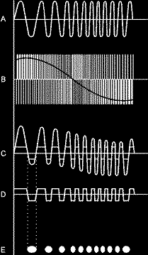
Combining the FM modulated analog video signal (A) with the digital
audio signal (B) gives a special waveform (C), which after topping (D), is
being used to burn the pits (E) into the master disc.
CD-i
Compact Disc Interactive was designed to make high-quality interactive
multimedia available to the general public. Invented by Philips, the CD-i
standard has been defined as world standard. Any CD-i disc will play on any CD-i
player anywhere in the world, regardless of who published the disc, who made the
player, or what the local television standard may be, unless it is encoded for a
specific market.
With CD-i, all the information is digitized, whether it is audio (music,
narration, sound effects), video (animation, still video, full-motion video,
visual effects) or data (graphics and text). This makes it possible to
interleave all kinds of information and gives it great flexibility. Another
impressive feature of CD-i is the ability to adapt the amount of storage
capacity to the application.
The CD-i specification defines two physical formats: Form I and Form II. Form
I, with error detection and correction code, is similar to CD-Read Only Memory
(CD-ROM) formats, and is applicable principally to the requirements of text,
computer data, and highly compressed visual data. Form II, without error
detection or correction codes, is tuned to the requirements of real-time audio
and visual data. Thus, the CD-i System is capable of reading CD-ROM-compatible
discs and fully integrated CD-i discs, as well as CD-Digital Audio discs.
CD-i Use
The CD-i player can be connected easily to virtually any television and
stereo system, and is operated via remote control. The standard 5-inch CD-i
disc is loaded in the same way as an audio CD. Discs are easy to use and
require no special instruction or knowledge. Users can control the action on
the television screen and activate various selections highlighted by pointing
to and clicking on command areas on the screen (by means of a remote control).
CD-i is called interactive because the user can interrupt the running sequence
of a program to recall a certain choice, go back to a previous step, ask for
more detailed information, or perhaps request to have the explanation in
another language - simply by the press of a button.
CD-i Compatibility
Developed as a world standard, the CD-i player will play any CD-i disc,
regardless of make or manufacturer, or country of origin. In addition, the
CD-i player is fully compatible with:
     - CD-Digital Audio discs
     - CD-Graphics
     - Photo CD discs
     - CD ROM-XA "bridge" discs
CD-i Design: Balancing Quantity and Quality
The CD-i disc can hold a maximum of 650 million characters of data. This
may seem a lot in comparison with the average office PC's hard disc, but
audio-visual information requires a lot of storage capacity and this can be
used up quite quickly. The designer must make choices based on quantity and
quality trade-offs from the range of audio and video information.
Audio Possibilities for CD-i
Four basic levels of sound quality are defined in the CD-i specification:
- CD-Digital Audio 1 channel stereo (16-bit pulse-code modulation of
existing standard): Offers more than one hour of stereo sound of digital
audio CD quality.
- Hi-Fi Music Mode (Level A) 2 channel stereo or 4 channel mono:
Equivalent to LP music quality, offering the user more than two hours of
high-quality and noise-free stereo sound.
- Mid-Fi Music Mode (Level B). 4 channel stereo or 8 channel mono:
equivalent to FM stereo broadcast quality and takes up only 25% of the disc
space occupied by CD sound.
- Speech Mode (Level C). 8 channel stereo or 16 channel mono: equivalent
to AM broadcast quality, suitable for speech and background audio, and
occupies only 12.5% of the disc.
Each channel is equivalent to a maximum of 70 minutes of continuous playing
time. In the fourth audio level, up to 16 parallel channels are available,
which makes the CD-i disc uniquely suited for multilingual applications.
Video Possibilities for CD-i
The CD-i standard encompasses both video resolution and coding
requirements. There are two levels to which the resolution can be defined:
Normal and High. The normal resolution of 384 x 280 pixels is equivalent to a
domestic television set. High level, at 768 x 560 pixels, is the equivalent of
color monitors and future digital television receivers. Pictures are generally
non-interlaced, although interlacing can be used.
Natural pictures, such as photographs and movie clips, occupy about 325
kilobits (325.000 bits, 325 KB) per picture without interlacing, and 650 KB
with interlacing. To decrease throughput times and still maintain natural
picture quality, all natural pictures on the CD-i disc are compressed to 108
KB, with no visible difference between the compressed and non-compressed
pictures.
Video information can be stored in various ways:
- Four levels for images ranging from natural photographs to graphics,
animation, and complex graphics mixes. The number of full-screen images will
depend on the chosen image quality. A minimum of 6000 full-color,
full-screen photograph images can be stored on one disc at the high end, and
many more at the lower end.
- Up to 72 minutes of full-screen, full-motion, super-VHS quality video
with Level B stereo (Mid-fi mode) can be stored on one disc. This is called
FMV (Full-Motion Video).
- Four different visual planes, and a whole set of different special
effects, such as wipes, dissolves, etc.
Full-Motion Video
In 1990, the extension of the CD-i standard with Full-Motion Video (FMV)
was announced, at that time with only mono (B) sound. In the meantime, the
development in compression technologies has made it possible to improve
picture quality and to add, instead of mono sound, high-quality stereo sound.
Philips, Sony, and Matsushita decided to adhere to the MPEG (Moving Picture
Experts Group) standard as the extension for full-motion video on CD-i.
The MPEG audio and video standard, as adopted for FMV, allows CD-i title
designers to use video sequences in several picture formats (4:3 and 16:9) and
in combination with the variety of audio qualities. It is this combination,
MPEG/FMV with the functionality of CD-i the various video planes, the various
audio levels, and the real-time operating system, which makes it possible to
produce entirely new pieces of highly attractive software.
In order to run FMV on the CD-i player, a special digital video cartridge
is required. Some CD-i players already have one installed, while others can be
upgraded.
Synchronization
CD-i is distinguished by the system's ability to integrate audio, video,
and computer data. Synchronization is necessary to ensure that the information
read from the disc is directed correctly into the audio, video, and computer
processors, and that the corresponding pictures and text are viewed
simultaneously, together with any accompanying audio.
Synchronizing is not a matter of simply maintaining a constant distance
between picture and sound, particularly if multiple language audio tracks are
used for a common picture sequence. The information for all channels must be
mixed together in the data stream, and the time required for processing the
different elements cannot be known until the processing actually occurs. To
manage these variable sequence timings, CD-i employs a physical interleaving
process combined with data-driven interrupts.
The ability to merge or interleave all of these and play them back
perfectly synchronized at run-time is made possible by CD-i's unique operating
system, called CD-RTOS. (Compact Disc Run Time Operating System)
Other Compact Disc Technologies
Besides CD-i, there are more formats of Compact Disc technology in use:

Official logos for CD-DA, CD-G and Photo CD.
The Digital Audio Compact Disc (CD-DA)
The 12-cm/5-inch Compact
Disc Digital Audio, commonly known to the consumer as the CD, has been a
phenomenal success ever since the inventors, Philips together with Sony and
Matsushita, agreed the world standard and introduced it in 1983. The
silver-colored disc delivers high-quality digital stereo sound, and can also
carry limited amounts of simple text and graphics (e.g., notes, lyrics, and
information about the music and artists on the disc). With a suitably equipped
player (such as CD-i), a CD+Graphics disc can supply pictures to an ordinary
television set and stereo through a hi-fi TV set.
CD-ROM
Compact Disc Read Only Memory is a derivative of the CD-DA
and is the same size. Computer manufacturers saw the capacity of 650 million
characters of memory (equivalent to 250,000 A4 pages of text) as a major
opportunity, and got together to draw up a standard, and introduced it in
1985. It was mainly intended to be a carrier of text, and the format is unable
to interleave audio and visual data. Theoretically, any CD-ROM disc should
play on any CD-ROM player, but in practice, because of incompatible computer
systems and software, this is not the case.
CD-ROM-XA
Compact Disc Read Only Memory eXtended Architecture is
designed to compensate for the deficiencies of CD-ROM as a multimedia platform
by borrowing parts of the CD-i standard.
This means that it is a link between CD-ROM and fully interactive CD-i. An
XA card inside the PC supports interleaving of text, graphics, audio, and
pictures. However, it requires a special CD-ROM drive. Using CD-ROM-XA means
that it is possible to have XA "Bridge Discs" which will play on the PC at the
office and the CD-i player at home, abolishing the need for a publisher to
develop separate PC and CD-i versions of the same title.
Photo CD
Photo CD is a high-quality photographic storage medium
developed by Philips and Kodak. One Photo CD can store up to 100 digitally
encoded 35-mm photographs at resolutions of up to four times greater than
High-Definition Television (HDTV).
Customers take their rolls of film to the photo processors for developing,
and receive standard prints as they do with normal photo processing. On
request, the photo processors use a work station to read processed 35-mm
negatives and slides, and then write digitized pictures onto Photo CDs.
Customers receive a disc containing all the exposures on the roll. The photo
images can be accessed via a CD-i player or Photo CD player, and displayed on
normal television sets. The Photo CD player offers random access viewing,
zooming, panning, editing, and more. A Photo CD can also be played on a
CD-ROM-XA-equipped PC. Via the PC it can be imported into desk-top publishing
and other computer-based design and presentation systems for editing purposes.
The photo images on the Photo CD can be processed and printed like normal
negatives. Very high-quality prints can be made directly from the Photo CDs.
Color, sharpness, and granularity are similar to those of prints made on
photographic paper from original negatives, and will only be limited by the
resolution of the display.
Connecting the LD/CD-i
Although a SCART-RGB bus is the best connection to the TV set, not every TV
is equipped with such a connection. Therefore, the outgoing signal is also
converted to a CVBS signal which can be transmitted via both a CVBS-SCART bus
and a video (cinch) bus. The latter is not ideal, as the color and brightness
signals will then be transferred as composite signals, resulting in a slightly
lower color quality, as there will always be some sort of cross color. The audio
signal can be transferred via separate audio busses, but just like RGB, the
CVBS-connection offers high sound quality, as the sound is not influenced by the
video information, being transmitted separately. For sound, both Laserdisc and
CD-i players have digital audio output, so they can be connected to amplifiers
with digital input.
Laserdisc players can be connected to TV sets that only have an antenna
connection. Like a video recorder, the Laserdisc player has a built-in sender
(an oscillator), which generates a signal with a carrier frequency that
corresponds to the frequency of the assigned A/V channel. If a video recorder is
already connected to the TV by antenna (HF), the Laserdisc player can be
installed simply by connecting all three devices in a loop. The TV antenna
should be connected to the antenna input of the Laserdisc player (ANT-IN). Then
the TV-OUT connection of the Laserdisc player must be connected to the antenna
input of the video recorder, via a coax antenna connection cable. Finally, the
output of the video recorder will be connected to the antenna input of the TV
via a similar coax antenna connection cable.
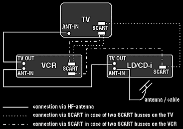
Connecting TV, VCR and LD/CD-i player.
As this connection takes place via the antenna looping amplifiers installed
in the Laserdisc player and the video recorder, both devices should always be
plugged into the power supply, putting them automatically in Stand-By mode. It
might occur that if the VCR is already tuned to the A/V channel and the
laserdisc player is also tuned to the same channel, interference problems on the
TV screen can be the result. To avoid such interference, the small tuning screw
at the back of the Laserdisc player called '+ CHANNEL -' must be turned just a
little bit, so that the signal is transmitted via another channel. As soon as
the images of both the video recorder and the Laserdisc player are displayed
without distortion, the tuning is satisfactory.
If the TV set is supplied with two SCART busses (connections), both the video
recorder and the Laserdisc or CD-i player can be connected independently, which,
of course, would be the best solution. When applying a TV set with one SCART bus
and a video recorder with two SCART busses, it is possible to loop them via
these two busses. This is also possible with the VIDEO IN and OUT busses of the
video recorder.
© EXIL SERVICE 1992-2017
N.Bgd, Bul
Z.Djindjica 84, Blok 30 • E-Mail:
tvlcdservis@gmail.com • Tel/fax: (011) 3115-135
w w w . s e r v i c e . r s
www.service.rs
www.service.co.rs
www.service.in.rs
tv
servis popravka televizora dvd servis lcd servis servisiranje televizora lcd
plazma popravka monitora
industriska elektronika popravka dvr digitalni videorekorderi servisiranje
monitora


