Home video equipment can be connected in various ways. TV sets can be connected to VCRs, CD-i players, audio systems, cable antennae, etc. But some connections perform better than others. Much depends on at which level the signal is transferred.
As we have seen in television, home video signals consist of the following elements:
Since the total signal consists of discrete elements, these elements can be transferred in different stages or levels. In practice, there are four levels, which are:
The more a signal is transferred into its discrete elements, the better the quality of the total signal on the receiving end can be.
In case of HF (High Frequency; Radio Frequency) all the elements are transferred over one signal, meaning all the audio and video (color, luminance and sync) information mixed in one. In practice, signals that are transferred on HF level are TV signals that come in via satellite, private antenna or cable. Also video recorders and laserdiscs can be connected to the television via HF (antenna signal).
CVBS stands for Composite Video Blanking Sync. At this level, the color, luminance and synchronization information are combined in one signal. The audio signal is transferred separately.
Y/C offers better signal quality than CVBS. Here the color (C) information is transferred separately from the luminance (Y) and sync information. It is especially suitable for S-VHS recording and playback, because the S-VHS recorder makes use of the separate transfer of the color and luminance signal. Like with CVBS, the audio signal is also transferred separately.
RGB is the level at which the color and luminance information is separated into three different signals representing the three primary colors red, green and blue. The sync signal is also transferred separately. Interconnection at RGB level offers the best picture quality.
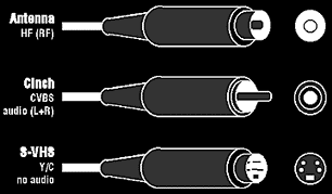
The antenna socket can be used to transfer HF signals. On every TV and VCR there is an antenna socket, which means that there is always a way to connect the TV to the VCR and to the private antenna or cable. In case decoder boxes are used, they are placed between the antenna income and the TV set. The color transmission systems must be the same on the sender and receiver side.
Cinch connections are used for three purposes and for each of these a different color of socket is used. Yellow is for the transfer of CVBS signals, white is for the left channel audio information and red is for the right channel audio information.

Antenna, cinch and S-VHS connections with sockets.
Y/C connections are also named S or S-VHS connections. There are four pins on the plug, one for the color signal, one for the luminance signal and two for ground. The squared pin at the bottom is to secure that the connector won't be plugged in the wrong way.
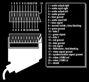
SCART (A/V Euroconnector) is a 21-pin connector. It allows trouble-free connection of all current and future A/V equipment. Besides audio and video signals, it can also transfer data and control signals. For example, a video recorder signal can automatically be put through the A/V connection. As soon as the VCR is switched on, automatically a control signal is transferred. so that various functions can be turned on automatically by SCART. With the SCART-bus, the antenna socket (the high frequency way) can be avoided. High End TV sets are supplied with more than one SCART-bus, which allows more than one video device to be connected, e.g. a video recorder and a CD-i player. The separation of the signals allows for better sound and image reproduction.

The SCART connection with pin number definitions.
In the SCART cable the in and out signals of audio and video are crossed. For instance, the VCR video out signal corresponds to the TV video in signal. This means that inside the cable, the wires are crossed (only the video and audio in and out signals).
In case a CVBS signal is transferred through a SCART it will use pin 20 (CVBS in) and pin 19 (CVBS out) to transfer the CVBS signal. The pins for R, G and B will simply not be used.
In case the Y/C signal runs by SCART instead of by the special S (Y/C) connection, the Y signal will run over pin 19/20 (CVBS in and out) and the C signal over Red signal (pin 15). The Y/C signal is sometimes referred to as the S-VHS signal.
In case of an RGB signal, pin 20 which is normally used by the incoming CVBS signal, is now used for the sync signal, and the separate R, G, and B pins are used to transfer each of the colors. It results in a sharper picture, less noise, better color contrast and better contours.
© EXIL SERVICE 1992-2017
N.Bgd, Bul
Z.Djindjica 84, Blok 30 • E-Mail:
tvlcdservis@gmail.com • Tel/fax: (011) 3115-135
w w w . s e r v i c e . r s
www.service.rs
www.service.co.rs
www.service.in.rs
tv
servis popravka televizora dvd servis lcd servis servisiranje televizora lcd
plazma popravka monitora
industriska elektronika popravka dvr digitalni videorekorderi servisiranje
monitora