The TV set is the central element of any audio/visual setup. It allows us to watch programs received by antenna, cable or satellite, and movies via our VCR. We can also use the TV as a monitor to play games on game computers and CD-i players.
In the following chapter, we will take a closer look at how images and color are made, and what systems are used to create these images. Further, we will look at how images and sound are broadcast, and developments we might expect for the future.
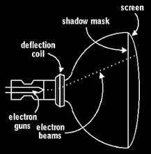
The central component of a TV set is the cathode ray tube (CRT). The components of a cathode ray tube are: the cone, the screen, the electron gun, the deflection coil and the shadow mask.

Side view of the picture tube.
The cone and the screen are welded together to form a glass envelope into which the shadow mask and the electron gun are positioned. The deflection coil is placed around the outside of the neck of the cone.
The inside of the screen is coated with light sensitive red, green and blue crystals called phosphors. These phosphors are arranged in groups of three (or triads) of one blue, one red and one green. Three electron beams are generated by the electron gun, one for each color, which directed by the deflection coil scans the screen moving left to right and up and down. The phosphors light up in the relevant color when they are illuminated by the beams.
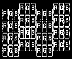
Placement of the red, green and blue phosphors on the screen. A group of one red, one green and one blue phosphor is called triad.
In order to produce a correctly colored image, each electron beam must hit only the appropriate colored phosphor. To ensure such accuracy, a shadow mask is used as a filter. The shadow mask is a metal plate which is the same shape as the screen and has the same number of holes as the number of triads on the screen. Each hole has a corresponding triad of phosphors which prevents adjacent triads from being influenced.
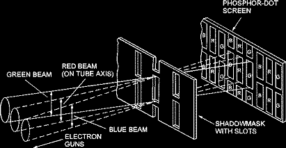
The shadow mask makes sure that the electron beams are aligned and strike the right phosphors.
The beams of the electron gun must converge exactly at the holes of the shadow mask, so there must be an alignment of the beams onto the mask. This is performed by an electromagnet within the gun.
The electro magnetic deflection coil surrounds the neck of the picture tube, ensuring accurate deflection of the beam. Electrical signals transmitted through the deflection coil generate precisely focused magnetic fields. These magnetic fields control the position of the electron beam vertically and horizontally.
Beam movement
The electron beam moves in lines, from left to right and from top to bottom. In most European countries the screen is made up of 625 (horizontal) lines. The number of lines on the screen determines the picture detail.
When the beam reaches the end of a line, it returns at greater speed to its original starting point. When it goes back, brightness is suppressed for a split second. Then it moves down two lines and the process repeats itself (see 'Interlacing' for further explanation). When the beam has reached the end of the bottom line, it restarts (with a split second interruption in brightness) at the top line.
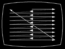
Front view of a TV screen showing the path of the electron beam.
Precision in Line
In a color TV, there are three cathodes, each generating an electron beam for one of the primary colors. In the early color TVs the three electron beams were placed in a triangular orientation. This was called the delta setup. As the pixels are round, this setup caused much of the light to disappear between the dots. Nowadays, the in-line system is applied (called Precision In Line), in which the electron guns are placed in a horizontal line.
Interlacing
The picture is created by firstly all the odd lines (1, 3, 5, 7, 9 etc...625) being scanned from left to right and from top to bottom and followed by a scan of all the even lines (2, 4, 6, 8, 10 etc...624). The result is that a single scan creates only half an image. In a 50 Hz TV, one scan takes 1/50 second, so to make two half images it takes 1/25 second. In other words, every second 25 complete images are formed. As the process of scanning two half images takes place in only 1/25 second, to the human eye the two halves appear to be one. This process is called interlacing. Fifty half images are formed per second, making up 25 whole images. This interlacing technique means the picture will show less flicker than if the beam were to scan all lines at once. The frequency of scans is called the raster frequency which is 50 Hz (50 scans per second), whereas the line frequency is 25 x 625 = 15,625 Hz.

The principal of interlacing: two half images making one complete image.
Line and Image Synchronization
The image and the reproduction must be synchronized perfectly. This will ensure that each picture element picked up from the camera target is reproduced in the right place on the display.
There are two kinds of synchronization (sync) pulses: line and image. The line sync pulse ensures that a line is reproduced correctly (i.e., what is at the beginning of a line, is reproduced at the beginning), and the image sync pulse is to ensure the whole image is reproduced correctly (i.e., the transmitted top line will be the reproduced top line). These sync pulses are transmitted with the picture signal. They do not control the electron beam of the tube in your TV set, because this could seriously damage or affect the image. The actual scanning movement of the electron beam in the TV set is directed by two deflection generators. These are continuously synchronized by the synchronization pulses generated by the camera. Even if there is no incoming signal, the electron beam in the TV set is continuously moving.
Color
In a black-and-white TV set, only one pixel type covers the entire screen. A black-and-white tube therefore only needs a single cathode gun. Variation in the brightness of the beam determines how much a pixel will light up, resulting in shades of black/white.
A color tube has three beams: one for the red, one for the blue, and one for the green pixels (phosphors). The three electron beams scan the screen as if they were one. The screen is covered with three types of phosphor dots and each type lights up in one of the primary colors of red, green or blue when it is struck by an electron beam. (The primary colors of red, green and blue [RGB] form the basis of all other colors.) A complete picture on a 28" TV contains approximately 450,000 pixels.
The ratio of the illuminated phosphors determines the total color. If, for instance, the beam that strikes the blue phosphor is suppressed, allowing only the red and green phosphors to glow, to the human eye the red and green will blend together to form bright yellow. By varying the brightness of one or more electron beams, the color pattern changes accordingly, which means that every possible color in varying brightness can be generated. When the camera scans a bright image, the transmitted signal has a higher voltage than when scanning a dark image. The electron beam in the tube immediately responds and the same relative brightness also appears on the screen, pixel by pixel.
Luminance and Chrominance Signals
When color transmission became a reality, it was decided to make the color TV transmissions compatible with the existing black-and-white TV. The black-and-white sets should then be able to receive the color TV transmissions and display them as normal high-quality black-and-white signals. In order to achieve this, the color images are split up in brightness (luminance) and color (chrominance) signals before they leave the transmitter.
The brightness or luminance signal
The brightness or luminance signal (Y) is transmitted via normal, full bandwidth, enabling a black-and-white TV to show a normal black-and-white picture. The white light needed for the luminance signal is made up out of 30% red, 59% green and 11% blue.The color or chrominance signal
Apart from luminance, two other characteristics make up a total color. First, there is the hue, which is the actual color (blue for example). Second, there is the saturation of the color, which is the depth of color, that makes the blue a light or a deep blue. The hue can vary from deep to pale, and the amount of color is its saturation. On a TV, a less saturated image has more white.The chrominance signal (C), which contains the hue and saturation, is modulated to a special color-difference signal. Since the luminance information is already being transmitted, the color signal doesn't need its brightness information anymore. The three color-difference signals are therefore: red minus the luminance signal (R-Y), green minus the luminance signal (G-Y) and blue minus the luminance signal (B-Y).
There is no need to transmit all three color-difference signals because when two ratios of the total chrominance signal are known, the third one can be calculated. For example, when there is 50% blue and 40% red in a specific color, the green must be 10% (50% + 40% + x = 100%; x = 10%). The two color-difference signals chosen for transmission are the R-Y and B-Y. The G-Y is omitted for signal-quality reasons. Since the Y-signal is made up out of 59% green, G-Y must have the smallest difference signal. The relatively small G-Y signal would be more vulnerable to noise in the transmission system than the larger R-Y and B-Y signals. Only using two of the three color-difference signals leads to a decrease in the amount of information needing to be transmitted.
Cross Color And Cross Luminance
Sometimes the luminance and chrominance signals are mistaken for what they are in the TV set. It can happen that Y signals are seen as C signals and the other way around. Cross color occurs when a luminance signal is mistaken for a chrominance signal. This becomes visible in picture patterns with regular structures of lines close together, such as checkerboard patterns.
When a chrominance signal is mistaken for a luminance signal, it is called cross luminance. It appears as a colorless "string of pearls" at edges of colored areas. Filters which improve separation of these signals are called comb filters and may be analog or digital filters. The digital comb filter is an improvement on the analog filter as it is better able to separate the Y and C signals.
After the color-difference signals R-Y and B-Y are modulated, the two are mixed to one signal in the transmitter. Demodulating the same signal in the receiver is a rather complex process, which has been solved in different ways in different countries. This has resulted in three major non-compatible systems worldwide, which are NTSC, PAL and SECAM.
NTSC
Around 1950, the NTSC system was developed as the first color TV standard. This basic color system works well, and after 40 years is still in use in North America and Japan. NTSC stands for: National Television System Committee, which was the organization that defined this color TV standard. NTSC is based on 525 picture lines and 60 Hz (60 scans across the screen in one second). The major problem with NTSC is that hue errors might occur. In order to correct this, all NTSC receivers are equipped with a special hue control.
PAL
PAL stands for: Phase Alternating Line and was introduced 15 years after NTSC. The system is based on 625 lines and 50 Hz. It has more picture detail than NTSC, because it uses 100 more lines and is able to write colors with greater accuracy. If there is a color distortion on one line, it will correct this on the next line by reversing the error. If, for instance, the intended green shifts to a yellow, on the next line it will correct this with a reverse error. The result is that the next line will be cyan (blue-green), which results in an optical green; the yellow and cyan will blend to green.
The major disadvantage of the PAL system compared with NTSC, is that it makes use of 50 scans per second rather than 60. This results in flicker and a more unstable picture. However, the problem of flicker is solved when the raster frequency is adjusted to 100 Hz (100 scans per second). 100 Hz TV will be discussed later on in this chapter. PAL is the most common system in most of Europe and Asia.
SECAM
SECAM or Sequence Couleur à Mémoire, (which translates as color sequence in memory) was developed around the same time as PAL. Whereas with both NTSC and PAL color errors still occur, with SECAM there are no color errors. The two color signals R-Y and B-Y are separated with a slight time difference, so that R-Y can always be recognized as R-Y and B-Y always as B-Y. Due to this separation, the resolution in color is being halved. SECAM is used in France, Eastern Europe, Russia and Africa.
The systems are not compatible because of the difference in the number of lines and the raster frequency, and the way they handle color reproduction. For those who want to watch movies recorded in a different standard, TVs and VCRs have been developed which are able to handle two or three systems. Conversion of TV, satellite or cassette programs to other systems results in lower quality.
Sound is becoming increasingly important in television. The sound supports the image and adds another dimension to make the viewer feel more involved. TV sets come in mono, stereo and hi-fi. Properly installed loudspeakers send the sound forward. Higher quality sets have low-frequency speakers that send their signals sideways and also have much smaller high-frequency speakers placed somewhere in the lower parts or to the sides of the set. As low frequencies travel in all directions, low-frequency speakers do not need to point at the viewer.
Speakers
While a TV set can be connected to hi-fi speakers, the main disadvantage is that the speakers are distant from the TV set. This often results in the sound coming from a different direction from the picture. This feels unnatural and is not a long-term solution. Therefore, stereo TV sets require matching loudspeakers, either built in to the right and the left, or placed right next to them as separate speakers. The best solution is special TV loudspeakers that are shielded to prevent magnetic emissions. When emissions from the speakers start to interfere with the electron beams, they can cause serious image distortions, especially color distortions.
Two Channel Reproduction and NICAM
Currently, many TV programs are broadcast in "stereo." In fact it is not just true stereo, but two channel reproduction. Stereo TV makes use of two fully separated channels, whereas a mono TV set simply receives only one channel, the main channel, which has the right and left signal information (L+R). The two-channel approach was chosen for TV because it allows for applications such as bi-lingual program transmissions. A movie can be broadcast over one channel in the original language and over the other channel in the dubbed language. In such cases the resulting transmission will be mono. In other cases the two channel approach can then be used for stereo broadcasting. Two channel reproduction is used in Germany, The Netherlands, Switzerland and Austria.
NICAM (Near Instantaneous Compending Audio Multiplex) is a digital sound broadcast system used in the UK, Belgium, Scandinavia, Spain and France. It uses three channels: one for mono and two channels for digital stereo or bilingual broadcasts. When broadcasts are bilingual, the sound will be mono.
Surround Sound
Surround Sound offers an additional dimension to sound. Many movies released on videocassette, Video CD or Laserdisc have stereo surround sound. Surround sound conveys not only the standard left and right stereo, but also the center channel information for dialogue and surround channel information for surround effects. The center channel information is transmitted as a mono channel which mixes the left and right signals. The surround sound goes in as a difference signal (left minus right) with noise reduction. Requirements for surround sound reproduction are a surround sound speaker setup and TV-audio/video equipment that can decode surround sound, and software recorded in surround sound. If the equipment is not able to decode surround information, it will reproduce the sound in normal stereo.
Dolby Stereo can be decoded in two ways for Dolby Surround Sound. The simplest form is called Dolby Surround. The surround channel is extracted and run through a Dolby noise reduction chip (with a little time delay of 15 to 30 milliseconds). The signal is sent to the speakers in the back of the room, which makes it sound more realistic. Dolby Surround Pro Logic adds even more excitement and is more advanced than Dolby Surround. It uses the center channel information to project dialogue from the front center speaker. Also the surround channel signal gives a more realistic sound. Whereas the center signal used in Dolby Surround is also reproduced in the front speakers, with Pro Logic this is not the case.
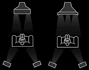
Left: a Dolby Surround setup. Right: a Dolby Surround Pro Logic setup, with center channel coming from the center of the TV.
Other Sound Features
Spatial
Spatial is a sound feature on some stereo TV sets. It can be used for both mono and stereo broadcasts, but it works differently in both cases. For mono broadcasts, the Spatial feature will create a pseudo-stereo sound from the mono signal. Spatial 'spreads out' the mono sound by reproducing it over two channels instead of one. The result is that it will sound 'fuller'. For stereo broadcasts, Spatial adds a kind of echo, or spaciousness and is particularly effective for action scenes in movies. This is achieved by mixing a part of the left channel information to the right channel information and vice versa. Not all TVs are equipped with this feature and its use is a matter of personal preference.Incredible Sound
This is a more sophisticated version of Spatial developed by Philips, which increases the sound stage width and depth in a more realistic fashion than Spatial.
Earlier on in this chapter we saw that it takes 1/25 second to transmit a complete picture, including all variations of black and white and all possible color variations. This is equivalent of scanning 1000 pages of a book within 40 seconds. Converted into an electrical signal, the amount of information would need a bandwidth of 7 MHz to carry it. To reduce the bandwidth to 5 MHz, the brightness and color signals (luminance and chrominance) are interwoven. In comparison, an AM radio station has a bandwidth of only 9000 Hz (4.5 kHz), whereas an FM station uses 75 kHz.
A carrier frequency is required to send a radio or TV signal. This carrier frequency needs to be many times higher than the frequency band that is to be transmitted. Carrier frequencies are allocated by international agreements to avoid interference in transmission which might occur if two stations were transmitting in or around the same frequency in the same reception area. The frequency range allocated for TV transmissions is between 41 and 960 MHz.
VHF and UHF Band
The total frequency range for TV is subdivided into five bands: bands I-V. These five bands are further divided into two large groups, namely VHF and UHF. VHF covers bands I-III and UHF covers IV and V.
     Band          Frequency (MHz.)          Used for
     ------------------------------------------------
     VHF
     I             41 - 68                   TV
     II            87.5 - 104                FM
     III           174 - 230                 TV

     UHF
     IV            470 - 581                 TV
     V             582 - 960                 TV
The VHF (Very High Frequency) band covers the area from 41-230 MHz. In this high frequency range there is room for a maximum of 12 TV channels. Band II of the VHF range is used for FM radio transmissions.
The UHF (Ultra High Frequency) band ranges from 470-960 MHz. This extensive range has a capacity of 60 TV channels. Some TV stations transmit in the VHF range, others in the UHF range. The range or frequency of the transmission has no effect on the reception quality. The reception quality is affected by antenna quality and adjustment, and occasionally by adverse weather conditions. As viewers usually want to be able to receive various stations to be found in both the VHF and UHF ranges, they use of combined VHF-UHF antennas. This applies to both private antennas and shared antenna installations.
S and H Band
Besides the above-mentioned VHF and UHF bands, the S (Sonderkanal, meaning Special channel) and H (Hyperband) bands are also useable for TV broadcast. They are separate from the VHF and UHF bands and can be used only by cable networks and shared antenna installations. The S-band is mostly used by shared antenna installations and cable networks to increase capacity. The frequency range is between 104 and 174 MHz, which is between band II and III of the VHF range. Any modern TV set can be tuned to the S-band.
The H-band (Hyperband) is reserved for future cable stations. Some of the more sophisticated TV sets are already prepared for the H-band. The frequency range of the Hyperband is between 230 and 470 MHz, which is between band III and IV.

Frequency bands VHF (I,II,III), UHF (IV, V), S and H (Hyperband).
Satellite Reception
Satellite programs are transmitted in the area between 10.7 and 12.75 GHz (10,700 and 12,750 MHz), also called the KU-band. These transmissions take place at much higher frequencies than the above mentioned bands, and cannot be received by regular TV tuners. Satellite reception therefore requires a special satellite tuner. Further information on satellite reception can be found in Chapter 6: Satellite Reception.
Transmission Ranges
One of the characteristics of the TV transmission frequencies VHF, UHF, S and H is that they are propagated in straight lines. As a result they disappear into the atmosphere at a distance of approximately 200 km from the transmission station. Consequently, their range is limited, and to be able to cover larger reception areas, repeater transmission stations are needed. The only way for TV stations to cover large distances directly without repeater stations is via satellite.
Screens are becoming increasingly flat and more squared. For better picture contrast, tubes are becoming darker. We will discuss projection television as an alternative to direct viewing, and we will take a look at the development of matrix displays as an alternative to the big and heavy picture tubes.
Flat Square Tube
A Flat Square Tube offers the viewer 9% more picture surface due to the squared corners and it makes the picture appear larger. Thanks to its flatter screen and the fact that there are no rounded corners, light reflection is decreased considerably and so subtitles and Teletext can be read much more easily. Flat Square is also known as Full Square.
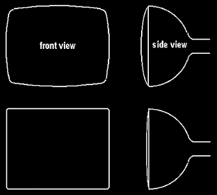
A standard tube (top left and right) compared with a Flat Square tube (bottom left and right).
Black Line Tube
The Black Line Tube, which can be recognized by its black screen when it is turned off, minimizes the loss of picture contrast in brightly lit environments. People are increasingly watching television during daytime, which means that their rooms are often filled with sunlight. Having darker screens and improved brightness levels, Black Line Tubes offer 50% better contrast. The result of this sophisticated tube is a sharp picture with high contrast, both at night and during the daytime.
Projection TV
For large screens it is not practical to use the direct-viewing system previously described. The weight, size, volume and the atmospheric pressure on the evacuated tube are the main reasons an alternative has been developed: projection TV. There are two approaches to projection TV-- back- and front-projection.
With both back- and front-projection TV, the light sources are three separate picture tubes with different phosphor screens built in, one each for R, G and B. The main requirement is high brightness, but this results in high temperatures. To withstand the great heat, the phosphor screens are made of sapphire or, a more affordable alternative, a forced-air cooling system is used. To gather as much light as possible and to project it on the screen, conventional lenses or a special Schmidt optical system is used. The lens or optical system gathers the scattered light rays from the tube and concentrates them into a parallel beam. This beam passes through a corrector lens on its way to the screen. As the tubes are situated alongside one other, the light beams strike the viewing screen from a slightly different angle, which causes the three color images to be out of alignment. In order to correct this, a convergence system is incorporated in the deflection system.
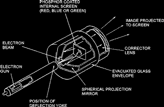
The Schmidt projection tube with an internal screen.
With back-projection TV a colored image formed by the three picture tubes is projected onto a large screen via a lens. Here the picture is built up on the rear of a ground-glass screen. Much depends on the required screen size and viewing area. To make a set smaller, a light path is often folded by an intermediate mirror and the image is formed on an integral screen.
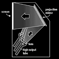
Back-projection TV.
Front-projection is where three separate RGB images are projected onto a viewing screen, where the projector and viewers are on the same side of the reflective screen.
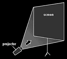
Front-projection TV. The projector projects three separate red, green and blue images onto a viewing screen.
Matrix Displays
Matrix displays have a discrete number of display elements (pixels) in horizontal as well as vertical direction. The pixels are interconnected by electrodes in a rectangular matrix of rows and columns. Selection of one particular pixel is achieved by addressing the corresponding row and column at the same time. Matrix displays can be either emissive or non-emissive. Emissive displays emit light directly from the display element itself. Plasma displays and Electro-Luminescent (EL) displays are emissive displays. Non-emissive displays do not emit light, but they modulate light. Therefore they are also called 'light valve displays'. Liquid Crystal Displays (LCD) and Digital Micro-mirror Devices (DMD) are non-emissive displays. LCDs use a light source from behind the display, DMDs have the light source in front of the display.
Emissive Matrix Displays
In emissive displays, the light is generated inside the individual cells (pixels). In monochrome plasma displays the cells are filled with plasma, which is a mixture of noble gasses, which lights up when the cell is ignited when an electric current passes through. For example, neon gives an orange-red light when ignited.In color plasma displays the cells are coated with phosphors which light up when the plasma is ignited. The type of phosphor determines the color of the pixel, just like in color TVs. Grey scales can be achieved by adjustment of the discharge current.
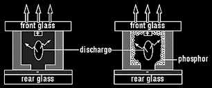
Left: A monochrome plasma cell. Right: A color plasma cell.
In Electro-Luminescent (EL) displays the phosphor generates light when a current goes through the cell. There are EL displays that use phosphors in each of the primary colors, and there are EL displays that use broad-band spectrum phosphors that, with the help of color filters, can produce the various colors.
Non-Emissive Displays
Liquid Crystal Displays (LCDs) contain liquid crystal molecules shaped like long cylinders. They are oriented in longitudinal direction and can be influenced externally by an electric field. By adding polarizers, the light can be modulated by the external electric field. When no electric field is applied, the molecules will be directed in such a way that they can function as light valves, so that light can be sent through. When the electric field is applied, the molecules will adjust themselves in the direction of the electric field and will not be able to let the light go through. Besides direct-view LCDs used for example in lap top computers, there are projection LCDs wherewith the viewing area can be enlarged.
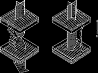
LCD cell with polarizers on the outside transmits the light if there is no electric field, and blocks the light with an electric field.
Digital Micro Mirror Displays (DMDs) have an array of electrically controllable mirrors fabricated in IC (Integrated Circuit) technology. The mirrors are made from aluminium and function as tiny display elements. DMD is a front-projection system where a projection lens is placed in front of the screen. There are only two ways a mirror can be positioned: one position in which the light reflects into the projection lens, and the other position in which the light is reflected outside the lens. Since the mirror only has two position possibilities, the mirror driving is done digitally. The only problem still is, that it can only guarantee the mechanical functions for 1,000 hours.
In television, digital image processing is becoming increasingly important. Some of the developments in this field are:
100 Hertz TV
100 Hertz provides a solution to the problem of area flicker, which is noticeable in 50 Hz televisions. As we saw earlier in this chapter, in 50 Hz TVs, the image is scanned 50 times per second - a frequency which is still detectable by the human eye in the form of a flickering picture. Every 1/25 of a second (every 40 milliseconds), one complete image is created. First a half image of all the odd lines in 1/50 second (20 milliseconds), then a half image of all the even lines in 1/50 second (20 milliseconds). (To simplify, we name the odd line image frame A and the even line image frame B). Even though this appears to be fast, one frame in 20 milliseconds is slow enough for the phosphors to fade to black before the next frame is sent to the screen. Due to the fading of the phosphors, we perceive area flicker. It becomes especially visible in bright areas of the image.
In 100 Hertz sets, the frames are scanned at a rate of 100 times per second, which is twice as often. To be able to double the number of image frames, 100 Hz televisions use a digital memory. The digital memory converts all incoming video signals from analog to digital. It stores every new frame for a split second, so that it can be written a second time (from memory) to the screen. After that, the digital signal is converted back to analog and sent to the screen twice as fast.
The A frame is sent to the screen twice within 20 milliseconds and then the B frame twice in 20 milliseconds. The doubling of the frames is refreshing the phosphors twice as often (every 10 milliseconds), which is so fast that the fading is not noticeable to the human eye.
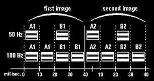
With 50Hz, the picture frames A and B are both sent to the screen once every 40 milliseconds. With 100 Hz, both A and B frames are sent twice to the screen in every 40 milliseconds.
Thanks to the use of a digital memory, 100 Hz technology offers additional possibilities for display, such as freeze, strobe and mosaic. Freeze enables you to "stop" the television picture so that you can have a closer look at any details. Strobe offers a step-by-step picture advance. Mosaic builds the multiple image in little squares, one from each of 9 selected channels, so that you can see what else is on.
Digital Scan (DS)
Looking at a television screen, small imperfections can be noticed in the horizontal parts of the picture, caused by line vibration (line flicker). Digital Scan is a Philips invention which is developed to remove line flicker. Together with 100 Hz, a totally stable image can be created.
Line flicker becomes apparent in horizontal details. Upper and lower horizontal edges seem to vibrate, because the edge is actually changing between the A and B frame (odd/even line changes). 100 Hertz solves area flicker, but not line flicker. Digital Scan uses the same number of frames per second as 100 Hz, but the frames are written to the screen in a different sequence.
In 100 Hz, first frame A is sent to the screen, then the same A again, then B and the same B again (AABB). Digital Scan writes first the A, then the B, then the same A frame again, then the B frame again (ABAB). The difference is that in case of 100 Hz, although there are 100 frames per second, there are only 50 frame changes per second, whereas with Digital Scan there are 100 frame changes. This is fast enough for the eye not to perceive any line changes. The result is an even more relaxing picture than 100 Hz.
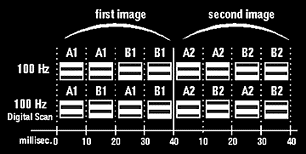
With 100 Hz, first the A frame is written twice to the screen, then twice the B frame. With Digital Scan, the A and B frame are continuously alternated, resulting in double number of frame changes.
Natural Motion
Natural Motion is building from the foundations of 100 Hz digital signal processing. In 100 Hz, each frame is repeated a second time (AABB). Natural motion uses these images in digital memory to estimate motion and create a new frame, which is inserted where the repeated field is in 100 Hz.
The newly created fields come in between and are created from the previous and next frame. The new A' frame is created from A and B, and the new B' from B and the next A frame. When there is motion between B and A, the newly created B' will average the motion, which makes the movement more smooth.
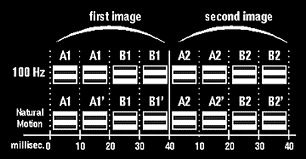
Natural Motion compared to 100 Hz signal processing. A1' is created from A1 and B1. B1' is created from B1 and A2.
Digital Noise Reduction (DNR)
By encoding signals digitally in 100 Hz sets, it is possible to clean up picture noise. This is beneficial on most transmissions, but especially in poor receiving areas, or from old videotapes.
Noise is a term used for the 'snow', the little dots, that appear on the screen when a TV channel is not received optimally. It becomes especially visible on large homogeneous surfaces from weak signals.
Noise can be caused by an old antenna, a cheap or damaged antenna cable, bad weather or when too many TVs receive signals from one antenna (which reduces the strength of the TV signal). Noise from the VCR can be caused by poor tapes, dirty or low quality heads or poor recording.
DNR makes a picture disturbed by noise more clear. Noise shows up as incorrect phosphors on the screen. What DNR does is that it compares the frames in the field memory: A to A and B to B. Then DNR notices any white individual phosphors which are surrounded by homogeneous phosphors. DNR replaces the wrongly encoded phosphor with the homogeneous surrounding color, so that it actually improves the received picture. The result is a clearer and sharper picture.
Dynamic Contrast
Normally, picture contrast is adjusted for the best balance between black and white (brightness/luminance levels). But it is complicated to get both black and white optimal for highest contrast. You can give priority to white so that it will be real white, but then the whole picture will be lighter. Or you can give priority to black so that the black will be as black as the picture tube permits, but everything will be darker (the blackest black is the color of the tube). After that, the setting is static, independent of how individual images are composed.
The already mentioned Black Line tube was introduced to make both black and white available at the widest range possible. But there is one more benefit to gain.
Specific images in a TV program contain different contrast. Most images are in only the darker, lighter or middle range of the scale. To make the black/white range wider (greater contrast), Philips has invented Dynamic Contrast. Dynamic Contrast uses the digital memory from 100 Hz. In the memory, Dynamic Contrast measures every A frame (= 25x/sec) and digitally analyzes where on the greyscale most of the image is located. (Is the image relatively light or dark?) If it is a dark image, the lighter part of that image is stretched more towards white, so that more contrast will become visible in the lighter parts of a relatively dark image. If it is a bright image, the darker part of that image is stretched more towards black, so that these darker parts will have more contrast. Most images are only in the middle of the greyscale, so both dark and light are stretched. We get more contrast steps added on both sides of where most of the image content exists. The benefits are that we get more nuances and details in most images, and a much greater contrast.
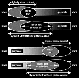
In an image which is relatively dark, the contrast in the lighter part of the image is streched towards white, so that total contrast range is increased. The opposite counts for a relatively dark image.
Teletext
Teletext is a system which transmits information via TV channels in the form of text and graphical reproductions. It offers information on TV programs, sports, up-to-date news, weather, travel and much more. The information that comes with Teletext is broadcast parallel with a normal TV program, or, when there are no programs on, with the test pattern. Almost every channel has its own Teletext service and Teletext is available as long as the TV station is on the air.
As we already know, a complete television picture consists of 625 lines. Only 580 of those are required to build the actual TV picture. The remaining 45 lines are used for vertical synchronization, test purposes and Teletext signals. The Teletext information is transmitted in digital format, via a maximum of 16 of the 45 remaining TV lines. The requirement for receiving Teletext is that the TV set must have a special Teletext decoder installed.
Poor reception of Teletext results in the reproduction of wrong letters and characters, or the disappearance of parts of the text. Good reception of Teletext is a more sensitive matter than TV reception. This means that if the reception of Teletext is good, the reception of TV signals will be good as well. This does not necessarily mean that when the TV signal is good, Teletext reception will also be good.
There are three kinds of Teletext: WTS, TOP and FLOF. WTS stands for World System Teletext and is the basic Teletext broadcast system. TOP (Table Of Pages), in addition to WTS, orders the pages in categories and adds other possibilities of enhancing ease of use. FLOF (Full Level One Features) gives information on next expected pages on screen. To be able to use TOP and FLOF, the TV set needs to have a TOP or FLOF decoder.
Teletext Level 2.5 introduces additional colors, including background colors. Also, 40 character wide text can be compressed into 2/3 of the screen width. The additional 1/3 can be used for graphics and additional text for reference.
Computer Controlled Teletext Digital signal processing also allows for special applications, such as Computer Controlled Teletext (CCT). CCT enables the storing of a number of Teletext pages in memory, so that you can retrieve them directly without waiting. The pages are continuously updated (even when they are stored in memory). When reading a page, it is also possible to enter the number of another Teletext page, which will then be retrieved and stored until needed.
Picture-in-Picture
The Picture-in-Picture display (PIP) is an option available on high-end TVs. By pressing a button on the remote control, a second picture, (coming from another connected source of video images,) will be displayed as a small inset in the corner of the main TV picture. The source could be a video recorder, a laserdisc player or a security camera. Because a video recorder has a built-in TV tuner, it is possible to display a second channel as a PIP-image. This enables you to watch one program, while keeping an eye on another. A PIP-image can be changed in size and moved about the screen. The inset picture can also be made the main picture and vice versa.
On-Screen Display (OSD)
By pressing the menu key on the remote control, a menu card appears on the screen. It enables you to make choices by simply entering a number, using the arrows or the +/- key. These choices cover TV installation, pre-defined channels, image and sound settings, and various special applications. This information can be retrieved on screen when watching a program. This digital feature is called OSD, On-Screen Display.
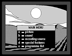
On-Screen Display (OSD).
The TV color test pattern is broadcast every day and is for the benefit of technicians and viewers to set their televisions to the optimum settings, to check if the TV and the antenna (or antenna system) are functioning properly and whether the video recorder is making satisfactory recordings. The test pattern is an electronically built image transmitted by the broadcaster. It can be used for setting color and black-and-white TVs. Although the test pattern does not look the same in the different European countries, it always contains similar picture elements to check the following:
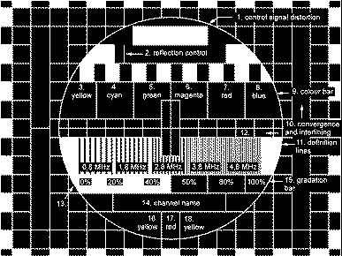
Example of a color test pattern.
Tuning
The name of the broadcast station identifies each channel. Definition lines are used to check whether the TV set is tuned properly. The lines graduate from thick to thin in blocks and should be visible as separate black-and-white lines. In some black-and-white TVs the thinnest lines will be visible as a solid grey field. This indicates that the receiver or the antenna is not performing to the highest requirements. Color TVs usually display the two blocks with the thinnest lines in a somewhat irregular, colored moire pattern, caused by cross color. This will happen when the test pattern is displayed from a video recording, as a video recorder is not able to process as wide a frequency spectrum as a TV receiver (3.2 MHz and 5 MHz, respectively). Only S-VHS can reproduce the thinnest lines clearly defined and without moire pattern, as S-VHS works with the full band width of 5 MHz and transmits color and brightness signals separately.Picture Geometries
The test pattern has an aspect ratio of 4:3. As the aspect ratio of conventional TV sets is also 4:3, the black-and-white fields at the edges are only partly reproduced. The large circle should appear as a perfect circle, and the surrounding chequerboard pattern should be made up of perfect squares. Image distortion reveals that the picture is not built up in a linear manner. Some TV sets allows the adjustment of the image with a control key at the back of the set. If there is no control key, an expert is required to solve the problem.Brightness and Contrast
Brightness can be adjusted with the help of the gradation bar, which goes from black to white. The black field needs to be perceived as black or, at least, as being very dark. Then, contrast should be adjusted in such a way that all shades between dark and light are clearly visible. There are four different shades of grey between the darkest black and the brightest white and all of these shades should be clearly visible.Color Reproduction
The color bar can be used to adjust color reproduction. There should be six standard colors visible seen as separate blocks. These colors are: yellow, cyan, green, magenta, red and blue. A moire pattern in the color bar indicates inadequate tuning.Interlacing
The two halves of an image that make up a TV picture should match exactly. When this is the case, all black and white lines inside and outside the test pattern circle have the same thickness.Convergence
All color televisions are self-converging. To check this, all horizontal and vertical white lines outside the circle should be truly white. Very small color deviations at the outer edges are acceptable, as long as they are not visible at normal viewing distance.Picture Synchronization
Whether the TV receiver is 100% in tune with the transmitter can be seen at the vertical white lines at the right hand side of the test pattern. A frayed zigzag pattern indicates inaccurate picture synchronization.Power of Antenna Signal
The grey background of the square pattern outside the circle indicates whether the antenna signal is powerful enough. The background should be solid grey with no colors. If enough colors are in evidence, something is wrong with the color decoder system of the TV receiver.Signal Purity
It is of vital importance that the incoming signal is well processed and reproduced by the TV receiver. Only then can the picture can be displayed in a natural manner. This can be checked by examining the black bar at the top of the circle. This bar should be perfectly rectangular and sharply demarcated from the white background. It should not have a white streak in it.Antenna Reflections
In the left upper half of the circle is a thin black vertical line. Only one line should be seen. If there is more than one, this indicates that the antenna signal is reflected. This can be due to for example a tall building in the neighbourhood, or an inadequate connection from antenna to cable or from cable to television. When normal TV pictures are displayed, double images will appear, which are out of focus, which are called ghost-images.Remaining Information
The color bars to the right and the left of the circle and the yellow-red-yellow segment in the bottom half of the circle add little information, unless you have specialist measuring instruments. An expert can use the indications to tune the color signals accurately.
Almost all aspects discussed above also apply to video recorders. When the normal TV reception is good, problems on VCRs can be identified by making a recording and looking at the recorded picture. The resulting recording will tell you whether the error is to be found in the video recorder or the videocassette.
Widescreen TV uses an aspect ratio of 16:9, compared with the common TV aspect ratio of 4:3. At a ratio of 4:3, the width of the screen is 33% more than the height, whereas at a ratio of 16:9 this is 75%. The 16:9 aspect ratio corresponds to the normal visual field of human beings. It will therefore feel more natural to watch and it is for this reason that most motion pictures are made in this format. Until recently, widescreen TVs were not made because of technical and cost reasons. It involves a different technique in creating the tube and since the production is only limited, it remains expensive compared with 4:3 TV sets.
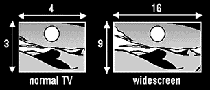
Normal 4:3 TV ratio compared to the widescreen 16:9 TV ratio.
To gain maximum advantage from a 16:9 set, the broadcasts must also be in 16:9 format. A 16:9 broadcast on a 16:9 TV set is the ideal situation. The complete image would automatically be displayed in full width and the viewer has all advantages of widescreen format. At present only a few programs are broadcast in widescreen, so it is more common to have 4:3 broadcasts on a widescreen set. In such cases, the screen is not completely filled and black bars are displayed to the left and the right of the image. So to make a widescreen set more suitable for viewing 4:3 broadcasts, widescreen sets come with several possibilities to fill up the screen.
Movie Expand is a feature to fill a 16:9 screen with a 4:3 broadcast. The 4:3 picture is 'blown up', or enlarged to fill up the black bars to the left and right. The image also expands upwards and downwards, so a part of the image on the top and the bottom 'falls off'. When a movie is broadcast in 4:3 and letterbox (with black bars on top and bottom of the screen), the black bars on the 4:3 image will fall off, and no part of the picture will be lost.
In some countries however, the lower part of a 4:3 broadcast is used for subtitling. Enlargement to 16:9 would result in a loss of subtitles. Tilted Movie Expand is a feature that enables you to move the image up and down, so that subtitles or titles can still be read.
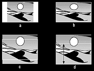
a) 4:3 broadcast on a widescreen TV.
b) 'widescreen' stretches out a 4:3 image to the sides to fill up the 16:9 screen.
c) 'Movie Expand' enlarges the 4:3 image to fill up the 16:9 screen, although parts of the image on the top and bottom fall off.
d) 'Tilted Movie Expand' allows the expanded eimage to be moved up and down.
Widescreen is an option on a widescreen set that stretches out a 4:3 broadcast to fill up the whole screen. In contrary to Tilted Movie Expand, no picture detail on the top and the bottom is lost, as the image is stretched out horizontally. The result is some picture distortion. An enhancement of this feature is Panoramic View. It stretches out a 4:3 broadcast, whereby the stretching is minimal in the middle and more to the sides. In the middle, which is the main viewing part on the screen, there will be no stretch distortions. At the sides it will be less noticeable and therefore less disturbing. In the meantime none of the picture is lost at the top and bottom of the screen. Subtitles, for example, remain undisturbed.
Widescreen Broadcasts On 4:3
There are several ways commonly applied to broadcast a 16:9 format movie or program on a 4:3 broadcast: Letterbox, Pan & Scan and Movie Compress.
Letterbox
In order to broadcast the whole picture as it was made originally, a lot of movies which are broadcast in 4:3 have black bars on top and the bottom of the screen. This method is called letterbox and the advantage for widescreen TV owners is that with using Tilted Movie Expand, the whole picture can be displayed on the screen, without picture loss.Pan & Scan
Pan & Scan is a method where a director in a studio decides which part of the 16:9 image should be cut off to get the best and most informative 4:3 image. This is more or less like sliding a 4:3 screen template over the 16:9 image. The disadvantage is that the viewer has no say in this, and he depends on the individual at the controls.
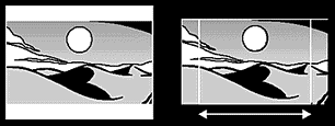
Letterbox (left) and Pan & Scan (right) as ways to put a 16:9 format movie or program on a 4:3 broadcast.
Movie Compress
The 16:9 image is squeezed proportionately, horizontally only. People appear thin on a 4:3 TV set. Widescreen TV users can choose the 'Widescreen' mode, and the image is stretched proportionately to fill the 16:9 screen.4:3 sets users can choose 'Movie Compress'. The 4:3 image is then squeezed vertically, to restore the original 16:9 proportion. On a 4:3 set, the viewer then will see letterbox.
D2MAC
MAC is a family name for systems devised in Europe for satellite broadcasting. MAC stands for Multiplexed analog Components but besides analog, digital information is added to this broadcast system, which includes sound information. MAC offers a good opportunity for secure scrambling and conditional access systems. One of the existing MAC systems is D2MAC and nowadays a few satellite stations broadcast in D2MAC. D2MAC was designed as an intermediate step between conventional systems and a universal High Definition TV system that is to replace the other transmission systems PAL, SECAM and NTSC. To be able to reproduce D2MAC signals, one needs a D2MAC decoder. These decoders can be connected to existing color TVs by means of a SCART cable or can be built-in.
HDTV
For many years, engineers have been working across the world to develop High Definition TV. This system will offer a picture quality that can be compared to that of a slide. HDTV means widescreen TV with movie theatre quality, CD quality stereo sound and language options. In two ways the technology will change: the aspect ratio and the number of picture lines. The transmissions will take place in 16:9 format, which is widescreen. The number of picture lines will be doubled, and the number of pixels will be quadrupled. This will ensure higher resolution and quality. As more information needs to be broadcast, HDTV works with a channel width of 12 MHz. The question whether it will become a worldwide standard cannot yet be answered. The development of HDTV is being marked by constant setbacks, and the Americans, Japanese and Europeans are not cooperating to come to a universal standard for High Definition TV.
© EXIL SERVICE 1992-2017
N.Bgd, Bul
Z.Djindjica 84, Blok 30 • E-Mail:
tvlcdservis@gmail.com • Tel/fax: (011) 3115-135
w w w . s e r v i c e . r s
www.service.rs
www.service.co.rs
www.service.in.rs
tv
servis popravka televizora dvd servis lcd servis servisiranje televizora lcd
plazma popravka monitora
industriska elektronika popravka dvr digitalni videorekorderi servisiranje
monitora
WWW.SERVICE.RS
WWW.SERVICE.CO.RS
WWW.SERVICE.IN.RS
tv servis popravka
televizora dvd servis lcd servis servisiranje televizora lcd plazma popravka
monitora
industriska elektronika popravka dvr digitalni videorekorderi servisiranje
monitora
Dusan Cubric dusan cubric